Improving an electric guitar
My trusty stratocaster was recently put on the surgery table for an autopsy and a full facelift. The objective was to understand how it works and see if I could give it a second youth.
I’ve bought this electric guitar a few years ago, it’s low-end chinese Stratocaster-like, purchased about 125 euros at the time. The sound has always been average and noisy, and with age, loss of voice became frequent.
As sending it to a luthier is not possible for a guitar of this budget, I decided to play the apprentice doctor and offer myself a makeover. Electronics lovers, get out your soldering irons! Guitar purists, maybe you will get a heart attack while reading this article.
An electromagnetic guitar
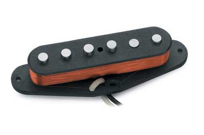
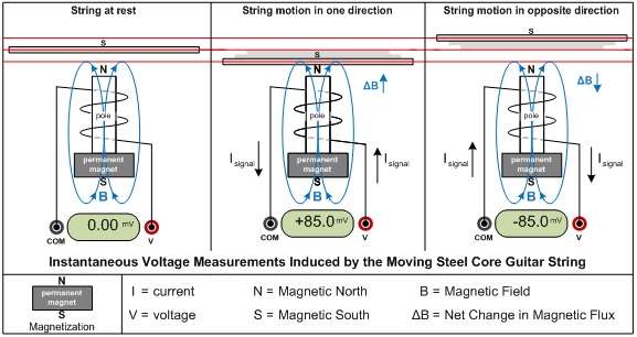
The operating principle of an electric guitar, or to be correct, an electro-magnetic guitar, is based on the low current generated by the microphones, which will then be processed by an amplifier and various effects before going out on top speakers. The single coil pickup, consist of a coil of copper wire in which magnetized rods are placed, one end of this magnet is apparent on the pickup cover. The vibration of the string, magnetized by the proximity effect, varies the magnetic field of the magnet, which has the effect of creating an induced current in the coil. This current then passes through various electronic components to arrive at the output jack. There are also several coils pickups (humbucker, etc..) but I will not cover them here, if you want to know everything about microphones, I invite you to read the article buildyourguitar covering a very comprehensive aspects of electronic microphones.
Dissection
To access the inner, relax all the strings and remove them, then unscrew the pickguard and if like me you have a budget guitar you will come face to face with a spaghetti monster, solderings made with feet, and low-end wood (which looks more like agglomerate). I unfortunately did not took a picture but I wrote down the diagram (for the form) and started unsoldering each component.
Caging
Noise in the sound of your guitar from external sources, and take the form of a hum at 50Hz (the one you hear near electrical panels) when you do not touch the strings.
To counter these negative effects, I use the principle of the Faraday cage, which involves placing sensitive components in a conductive cage.
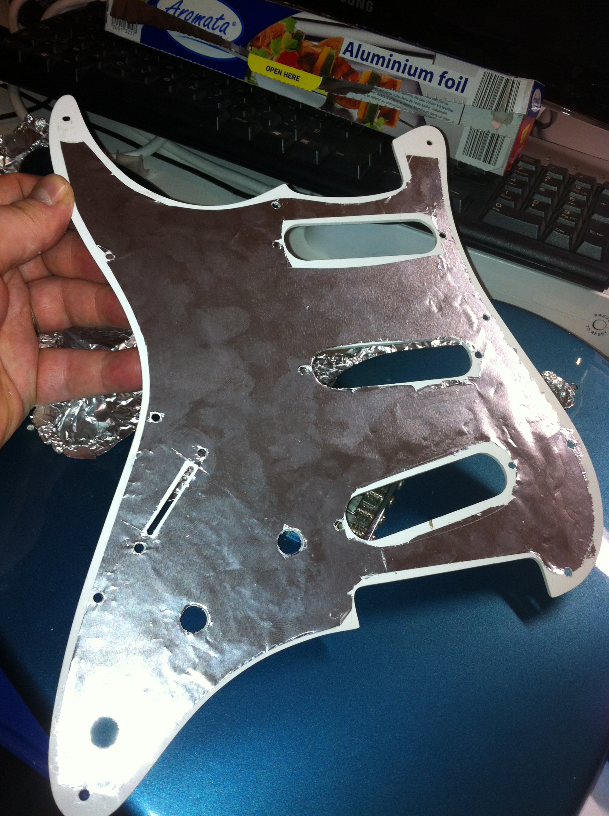
The necessary equipment can be found in any kitchen: aluminum foils will find a new use!
I first applied the glue (with a roller) on the inside of the pickguard, I then glued the foil, cut the edges with a blade and cleaned up the holes of the plate.
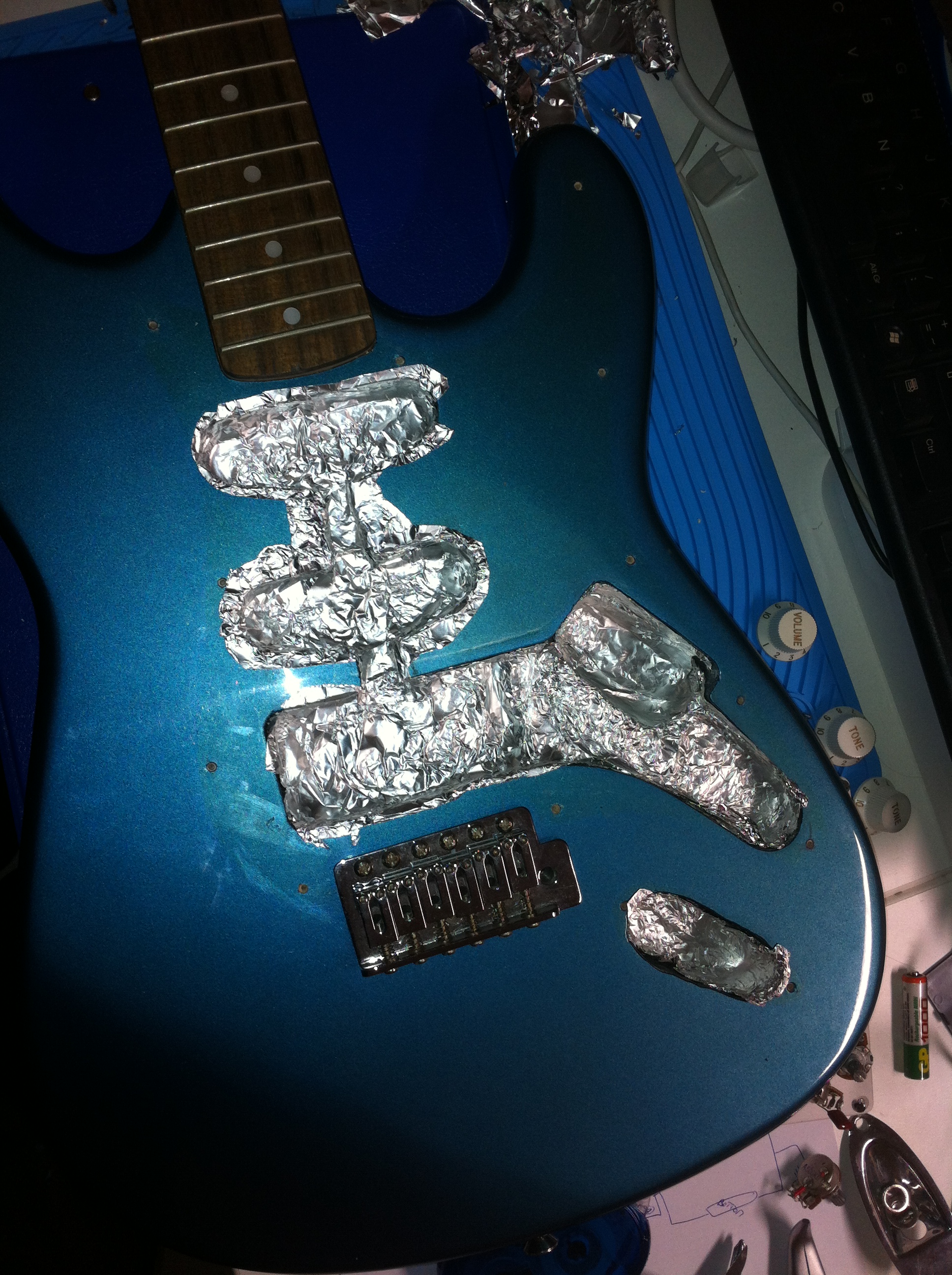
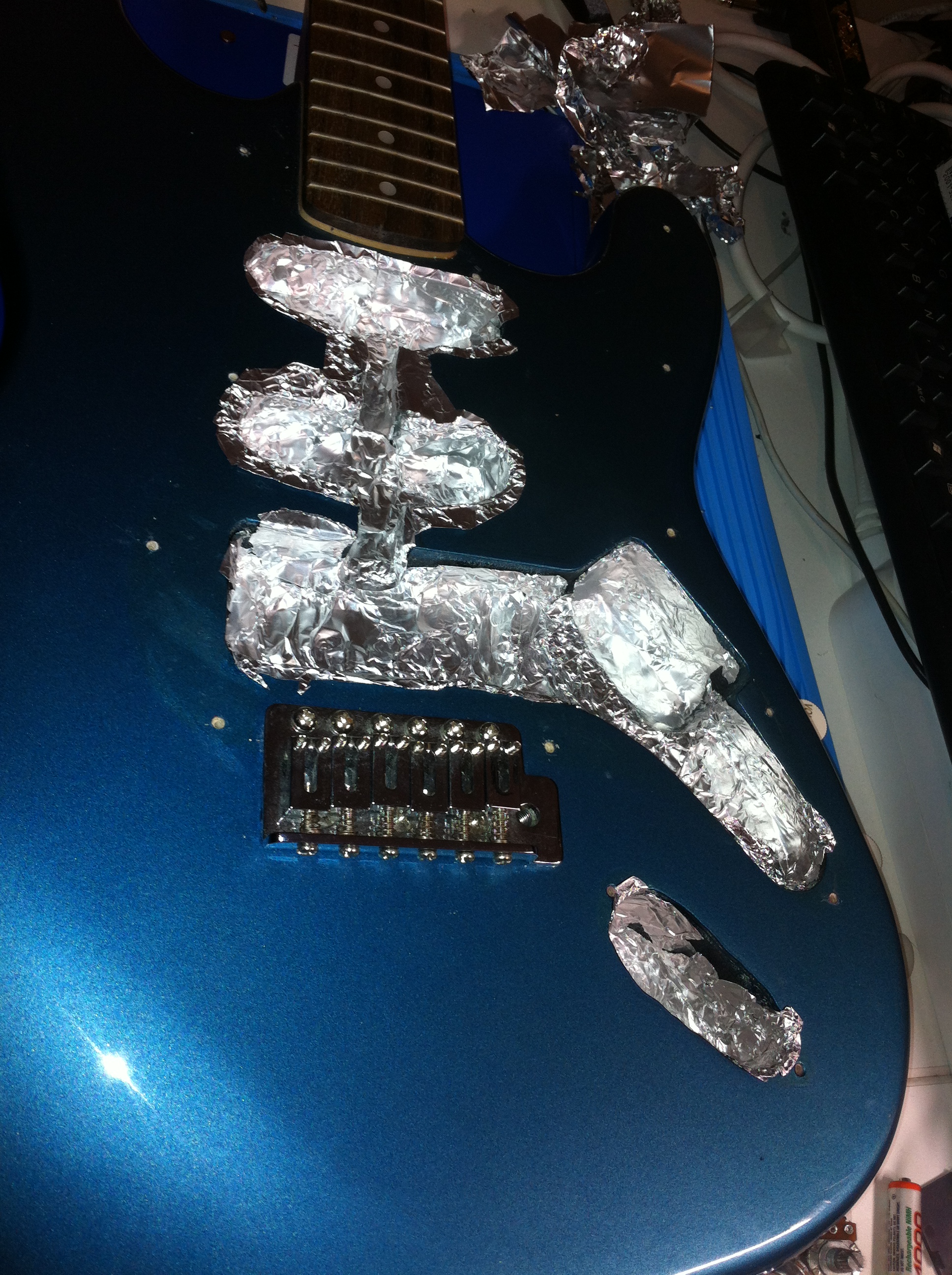
I also lined the inside of the guitar body with aluminum and glue (Loctite gel) and I used insulation tape to hold together the various foils and isolate where a short circuit could occur.
Electrocution
After analyzing the electronic diagram, I searched for variants on the net and my choice finally settled on one proposed by Bare Knuckle Pickups because it is simple, requires no additional hardware (at first) allows tone tunings on every position and enables noise-canceling in positions 2 and 4 of the selector switch(explained later).
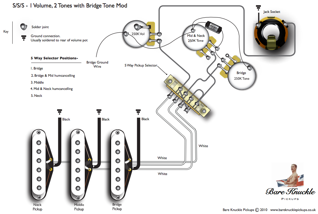
By observing the diagram, you can quickly understand how the various components work. The volume control is done through a voltage divider which, when the volume is set to “0” bypasses the output jack to ground.
The “tones” are series RC filter placed in parallel with the voltage divider, which is to create an effect of low-pass filter whose cutoff frequency depends on the potentiometer. By setting the potentiometer to “0”, the filter is activated to its maximum, blocking frequencies (harmonics) and only letting the bass.
Component Selection
With single coil pickups, it is recommended to use 250kOhms pots. No luck, mine are 500kOhms, the best would have been to buy new, and preferably logarithmic. Indeed, their logarithmic response allows sound to match the sensitivity curve of the ear, which gives the impression of a constantly changing volume when you turn the knob.
Still no luck, my knobs are not logarithmic nor linear, they are anti-log! This means that the volume increase sharply between ‘1 ‘and ‘5’ (approximately), and the passage from ‘6 ‘to ’10’ will not make a big difference. In itself, this problem does not bother me more than that, I can deal with it.
A quick test of my knobs confirms to me that they are really low-end, the measured value of internal resistor is sometimes far from the displayed value: up to 460kOhms for 500kOhms stamped pot gives us an error of a slightly less than 10%.
This is unfortunately not the only problem, they also suffer from the phenomenon of “crack.” The potentiometer is composed of a conductive brush moving on a carbon track, and when the track is worn, cracks or cuts begin to interfere with the sound. This phenomenon is very common on older amps and can be corrected by replacing the part.
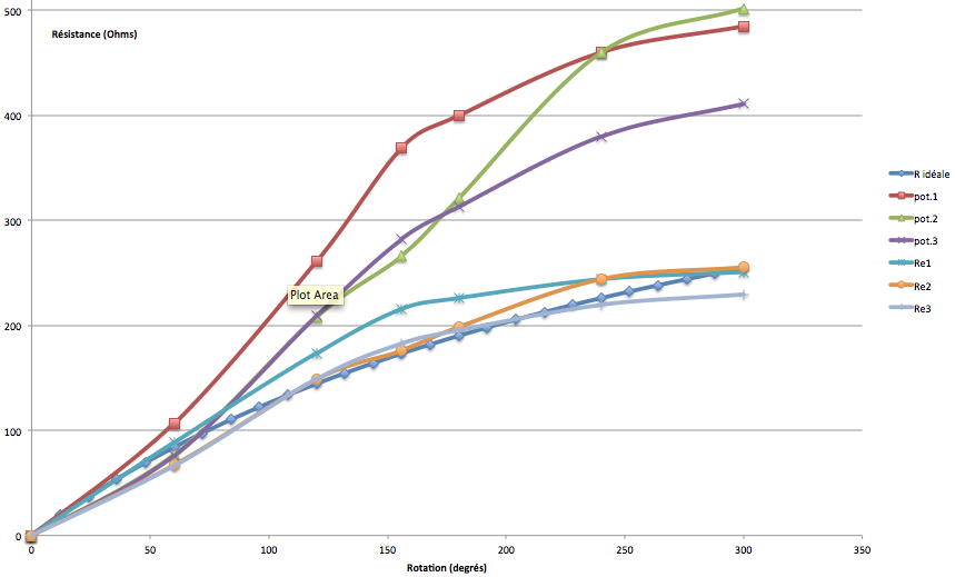
To achieve a resistor of 250kOhms, I placed on each potentiometer a resistor in parallel to decrease its value at the expense of an increased antilog effect. The equivalent resistor Re is found with the formula Re = (R1 * R2) / (R1 + R2) where R1 is the measured internal resistor of the pot and R2 is the resistor to be added in parallel to have a maximum equivalent resistor of 250kOhms.
In the diagram below, the ideal R is a linear 500kOhms knob with R 500kOhms in parallel, which makes antilog. I tuned the 3 resistors so that the curves fit to the ideal R (here the values are correct for Re1 and Re2 but not for Re3).
I also replaced the filter capacitor (0.033 microfarads) with a ceramic capacitor of 0.022 microfarads. It is made of three capacitors in parallel (capacities are added in this case) because I had no capa of this value under the hand and I did with the spare parts I had (two capacitors 103 and one 222) .
In the end, the schema has evolved to:
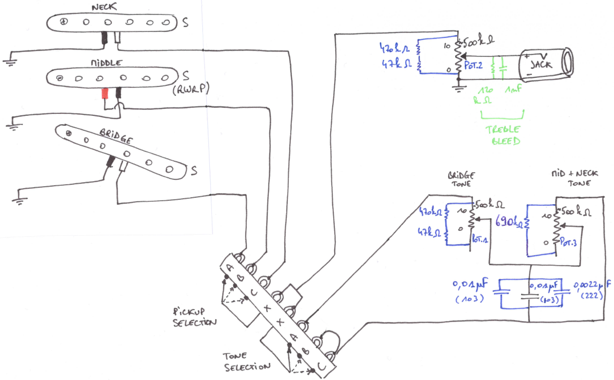
A few remarks about the diagram:
- The middle is a RWRP pickup (reverse winding, reverse polarity), wound backwards and reversed magnet. When combined with another normal pickup, the signals generated by the strings are added while the interfering signals are canceled. This gives a well rounded sound and gets rid of parasites, just like the humbuckers.
- The 5-way selector switch is not the same as the one provided by Fender, although its operation is identical. It is divided into two parts: the selection of the microphones and the selection of the tones. Depending on its position, it connects pin X to A, A + B, B, B + C, or C.
- The blue parts are the components that I added to correct values for my guitar. On another guitar, these values should be recalculated.
- The green part represents a “treble bleed”. This small plugin allows, when the volume decreases, to less attenuate the high frequencies and thus keep some treble at low volume. I’ve put it for information but I have not built in my project.
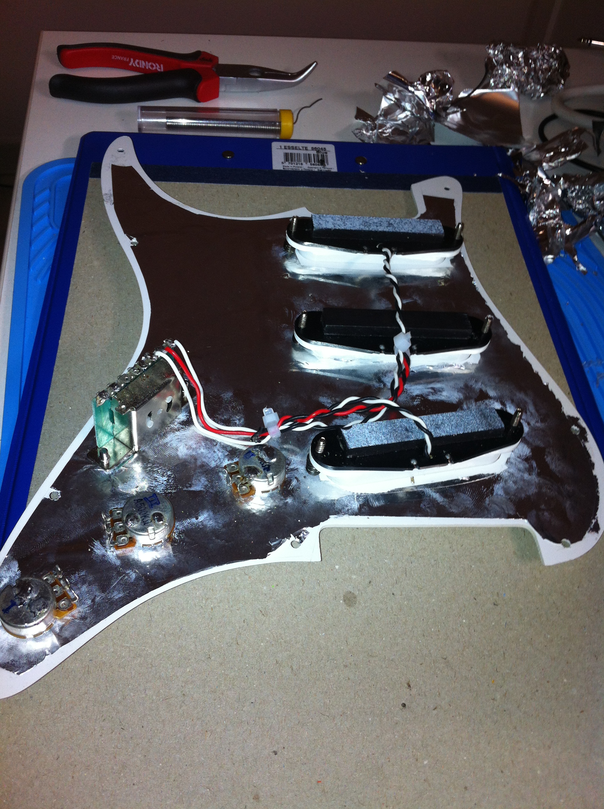
Soldering
It is now time to solder it all. start by placing the components on the pickguard.
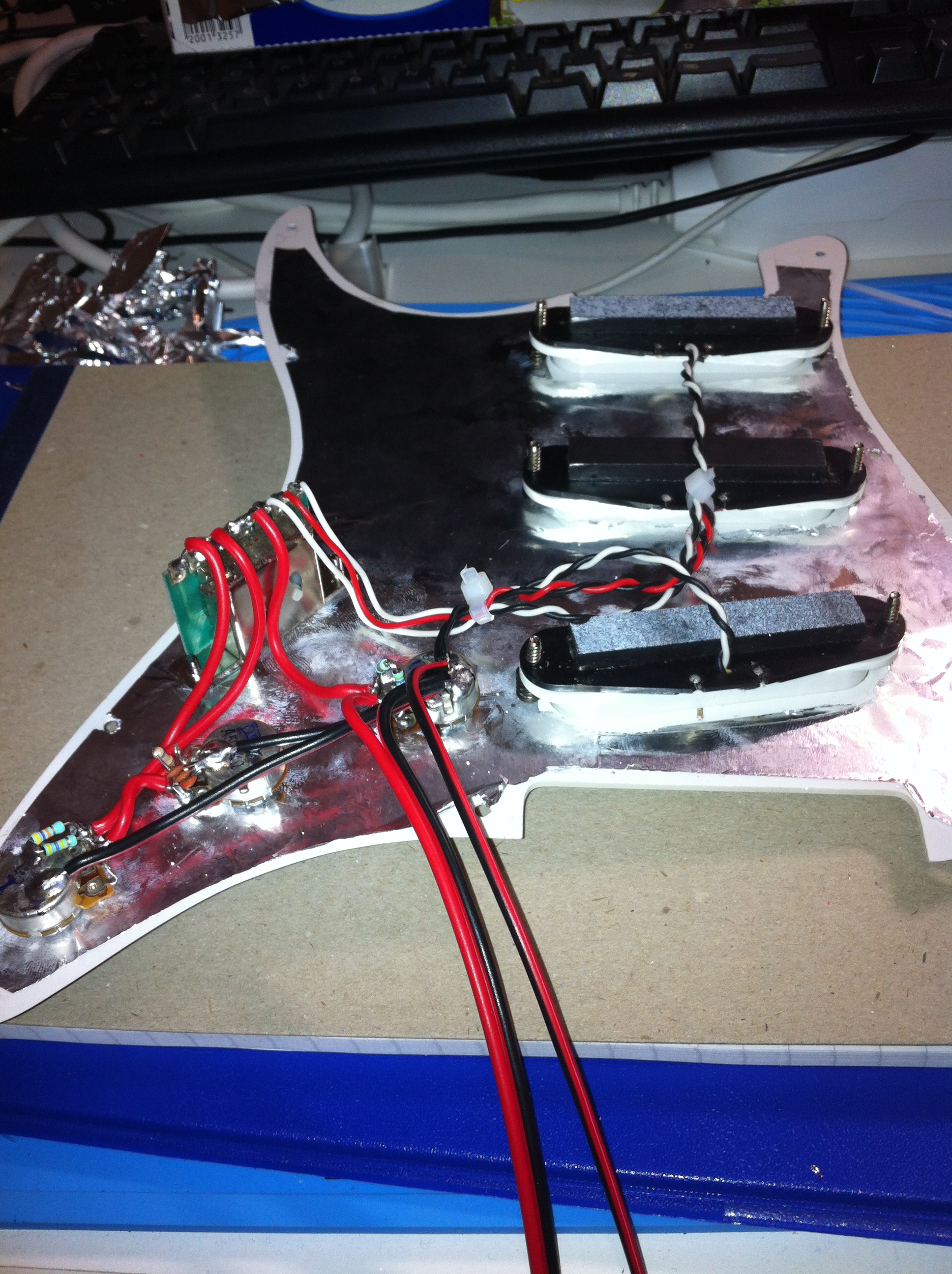
To further reduce noise, I twisted the cables of my pickups. This technique is also used with UTP cable for computer networks.
I replaced the original cables with audio cables that have the advantage of being bigger and of quality.
The ground points are gathered on the volume knob are 7 in number: 3 pickups, 2 tones, 1 jack and 1 for the springs on the back.
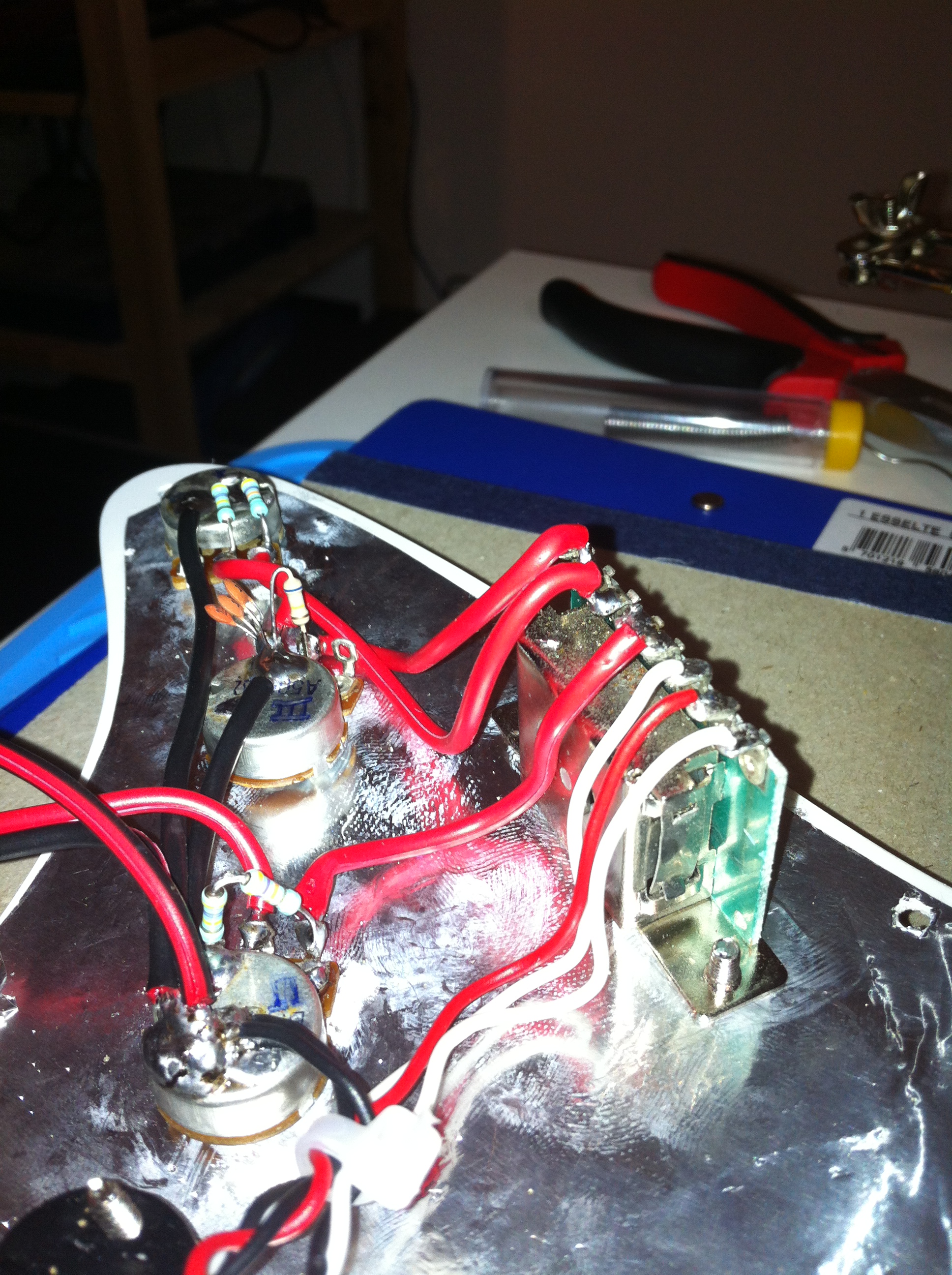
Make sure your soldering with a multimeter before the plate back in place.
Once the pickguard was back in place, I took one of my old strings to test the pickups. Everything worked except the volume knob. After some investigation, I found that the culprit was the potentiometer. The end of the carbon track was cut, so that the voltage divider, not being grounded, no longer played its role and left the volume to maximum. After a quick repair and a reassembly followed by a conclusive test, I put on my new strings.
Last tuning
To perform my last tuning, I followed this guide on audiofanzine.com.
Before tuning the guitar, I adjusted the height of the saddles and the bridge so that the strings are well away from the handle and do not curl. The length of bridges must be adjusted to match the 12th fret harmonic to the note of the chord. This tuning may be difficult, and requires to have a good ear and a straight neck.
Adjust then the height of the pickups. Too close, they will produce a distorted sound, too far, they will produce a low sound. I chose to take as a reference, when the string is fretted at 12th fret, for the low E, a distance of 2.7 mm from the lower end of the string to the top of the pickup, and for the high E a distance of 3.1 mm.
Final test
After all these operations, I finally got my guitar to sing again. And what a surprise! In addition to a clear and pleasant sound, the harmonics are well present. Potentiometers are still cracking but this was expected.
With this configuration, I have the feeling of playing on a new guitar. And even if its components are not well made, and we are far from the quality of an expensive Fender, the sound is clean and gives positive influence on the playing comfort
Tags: electronics, guitar